Replacing Marvin Next Generation Locks
Lock Handle Assembly Removal and Replacement
Removal
- Remove the bottom sash from the frame.
- Move the lock handle to the 135° “unlocked” position.
- Remove the left hand screw that was previously covered by the lock handle.
- Move the lock handle back to the 0° “locked” position.
- Remove the right hand screw.
- Lift the lock actuator off of the checkrail.
Replacement
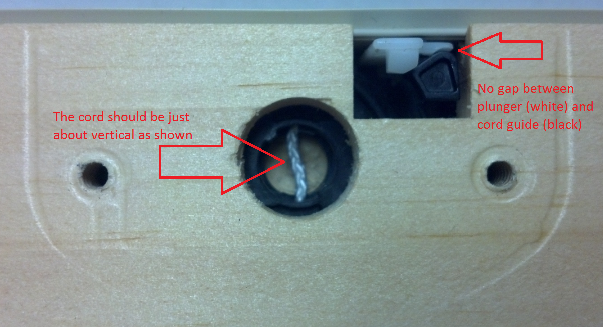
- Verify the position of the cord in the cord guide. See Below. If the cord does not appear to be in the correct position please refer to the cord guide replacement instructions.
- Verify the plunger is hooked on the cord guide. See Below.
- With the lock handle in the 0° “locked” position, push the lock handle assembly straight down onto the checkrail. You should feel a little bit of resistance as the lock handle engages the cord in the cord guide.
- Install the right hand screw
- Move the lock handle to the 135° “unlocked” position, verifying that the latch bolts move as you rotate the lock handle
- Install the left hand screw.
- Move the lock handle back to the 0° “locked” position.
Cord Guide Assembly Removal and Replacement
Removal
- Remove the bottom sash from the frame.
- Remove the Lock Handle Assembly.
- Remove the hardware cover. (vinyl part on exterior face of checkrail)
- Pull the cord guide assembly out of the biscuit cut.
- Flex the cord guide until the large spool pops out.
- Pull the cord out of the cord guide.
Replacement
- Place the cord in the cord guide as shown below, making sure to get the cord past the two retention features. See Figure 1.
- Place the large spool over top of the cord, using the alignment slots. See Figure 2.
- Rotate the large spool counter-clockwise until you hear two clicks. (about 270°)
- Place the cord guide assembly into the biscuit cut in the checkrail.
- Replace hardware cover.
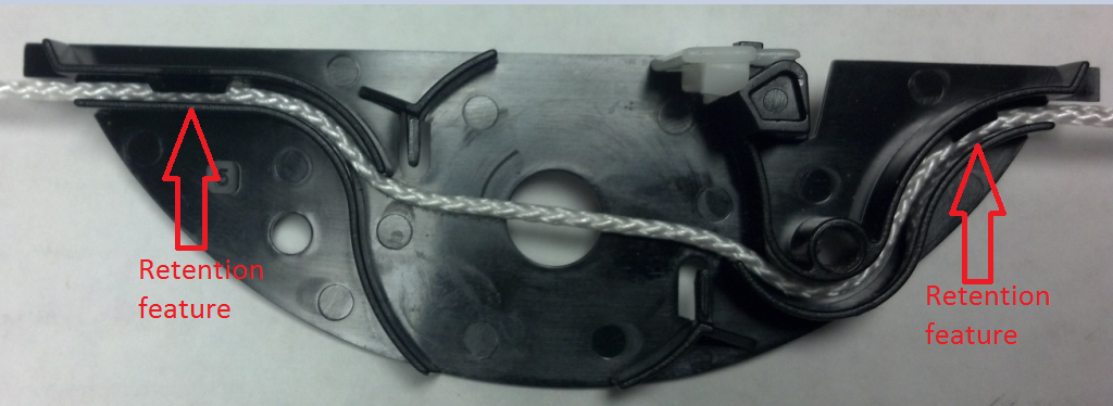
Figure 1

Figure 2
Bottom Sash Latch Assembly Removal and Replacement
Removal
- Remove the bottom sash from the frame.
- Remove the hardware cover. (vinyl part on exterior face of checkrail)
- Loosen the cord screw until the cord can be pulled free of the bolt.
- Remove the #6X1” and #8x 1 ¼” screws from the bottom sash latch assembly.
- Remove the bottom sash latch assembly from the sash.
Replacement
- Fasten the latch assembly to the checkrail using the #6X1” and #8x 1 ¼” screws.
- Wrap the cord around the cord screw. The cord must be as shown. See Figure 1.
- Remove the slack from the cord and tighten the cord retention screw.
- Move the lock handle to the 135° “unlocked” position and verify that the cord length has been set correctly. See Figure 2.
- Trim off excess cord.
- Replace the hardware cover.
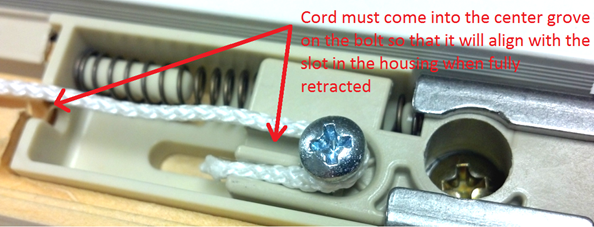
Figure 1
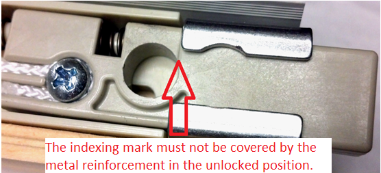
Figure 2
Balance Relocation Instruction
Removal
- Remove bottom and top sash
- Remove interior wood cover to expose bottom sash balances, or the exterior vinyl cover to expose the top sash balances.
- Disconnect the balances from clutches
- Remove the balance tube by sliding it off of the mounting stud.
- Secure a locking pliers to the mounting stud as close to the base as possible. See Figure 1

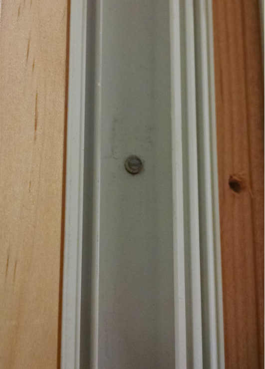
Figure 1 Figure 2
- Rock the locking pliers up and down to break off the mounting stud. See Figure 2
- Measure and mark the new balance location. If replacing with a longer balance tube, move the mounting location according to the balance length change. Ex. If replacing a 24B with a 28B the mounting location will move up 4 “
Replacement
- Install new balance with a #8 flat head screw that is a minimum of 1 ½” in length.
- Connect balances to clutch
- Replace covers
- Replace sash